


Beginning at the End
This project is an experiment in signal fidelity using cassette tapes as a medium as well as a test of the robustness of SSTV signals against the artifacts of tape. This end product is a gift for a close artist friend of mine who is enamored with the magic of tape.
I’m going to start at decoding rather than encoding because I do not yet have a cassette recorder. The decoding setup will be a portable cassette player connected to an Android smartphone with a custom adapter. I’m going be testing the created tapes with an app called Robot36. This is a free app that decodes a variety of common SSTV formats and has a simple interface.
Before I can start to play with formats I need to create a little hardware for use with my phone. Robot36 (and many other SSTV viewers) work by decoding an audio signal. Most modern smartphones (new iPhones excluded) have a TRRS jack that hosts stereo output as well as a microphone input that can be used to receive an SSTV signal. This input can’t be used for line-level input directly, so a simple adapter circuit will be built to attenuate the incoming line-level to mic-level.
In addition to adjusting the signal level, the adapter circuit will also cause the phone to detect an external microphone. Most phones detect the type of headset plugged in by measuring the resistance between the microphone and ground. Forcing the phone to use the external microphone input should be simple as placing the correct resistor across the mic and ground pins. According to the official spec Android phones detect an external microphone when at least 1kΩ DC resistance is present across the microphone and ground pins. I couldn’t find an official spec for the iPhone headset port, but an answer to this stack exchange question indicate a resistance around 1.6kΩ will activate the external microphone input.
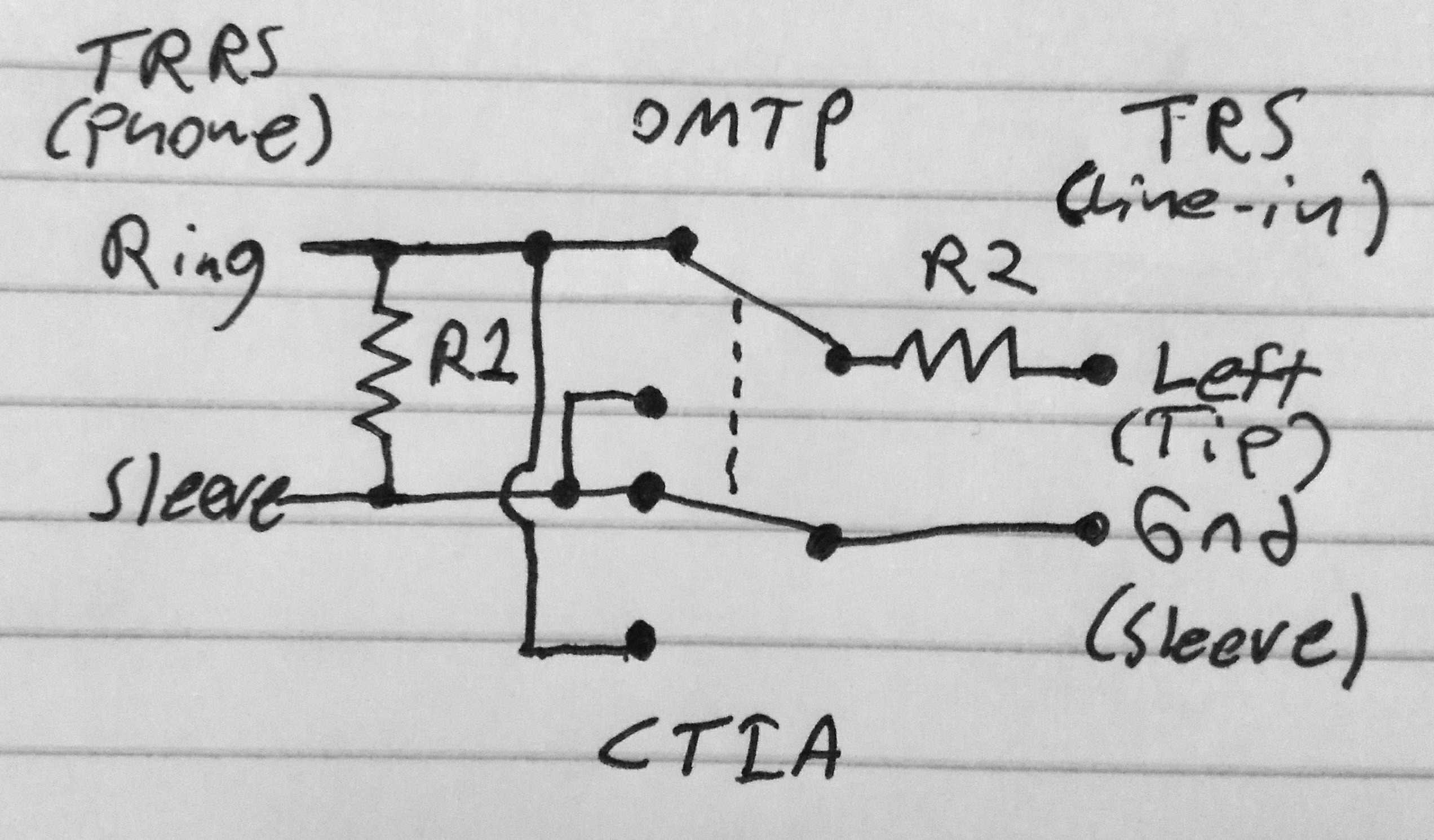
While the detection mechanism is similar, the pinout of Android devices and iPhones are incompatible. some older and Chinese Android devices use the OMTP standard and iPhones and newer Android devices use the CTIA standard. Luckily, the difference in pinouts is a swap of the mic and ground pins. A resistor can be placed across the ring and sleeve to cause both devices to detect an external microphone, and a DPDT switch can swap ring and sleeve to allow selecting between OMTP and CTIA pinouts.
Now there’s the problem of level conversion. A resistor on the line-input side of the switch completes a voltage divider (L pad) with the resistor across the ring and sleeve. This divider drops the signal from line-level to mic-level by attenuating the signal -40dBV (0.01 times). Note: -40dB seems to be common for commercial line-level to mic-level converters so that’s what I’m going with. Knowing the ratio of input and output voltage, the resistor values can be calculated. R1 is the resistor across ring and sleeve; R2 is the resistor from line-in to the selector switch. R1 can be fixed at 2kΩ for convenience making R2 about 200kΩ. Below is a schematic of the complete adapter circuit.
Once I acquire a couple of 3.5mm connectors and a switch I will be able to build and test this adapter out.
Edit: My original calculations used dB where they should have used dBV. I have since corrected the value of R2 from 20MΩ to 200kΩ.