


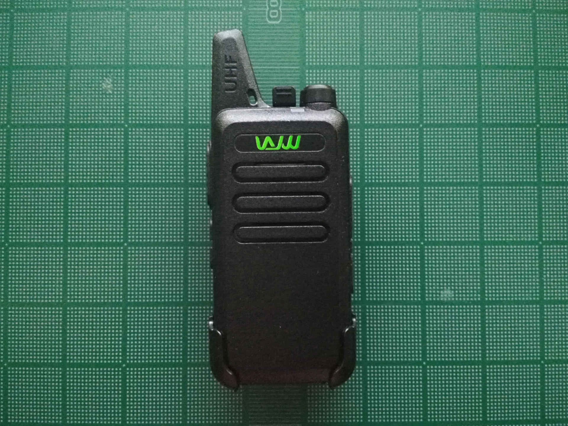
WLN KD-C1 Teardown
I tried to find a teardown of the KD-C1 before I purchased it. I managed to find a video of a partial teardown, but this video stops short of removing the PCB from the plastic case (for good reason as seen below). I decided to go deep and completely disassemble the radio as far as I could.
The belt clip and battery cover were easy to remove without tools. Below the battery cover there were 6 Torx screws holding the plastic halves of the radio together. One screw was hiding under the battery compartment label.
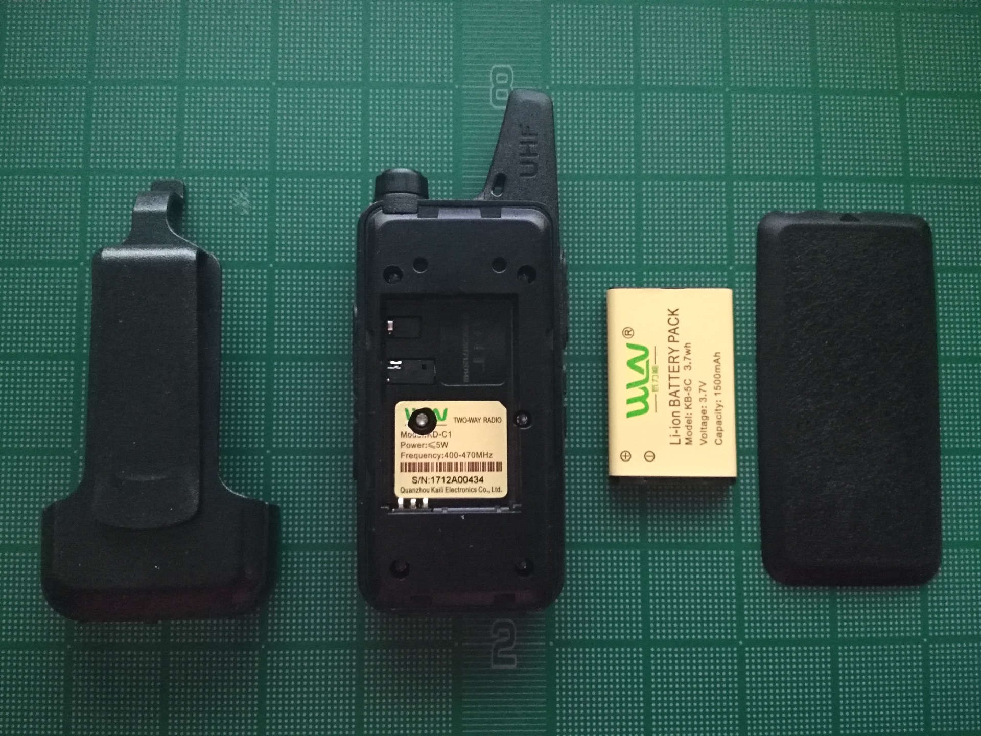
Once the screws were removed the two plastic halves separated easily.
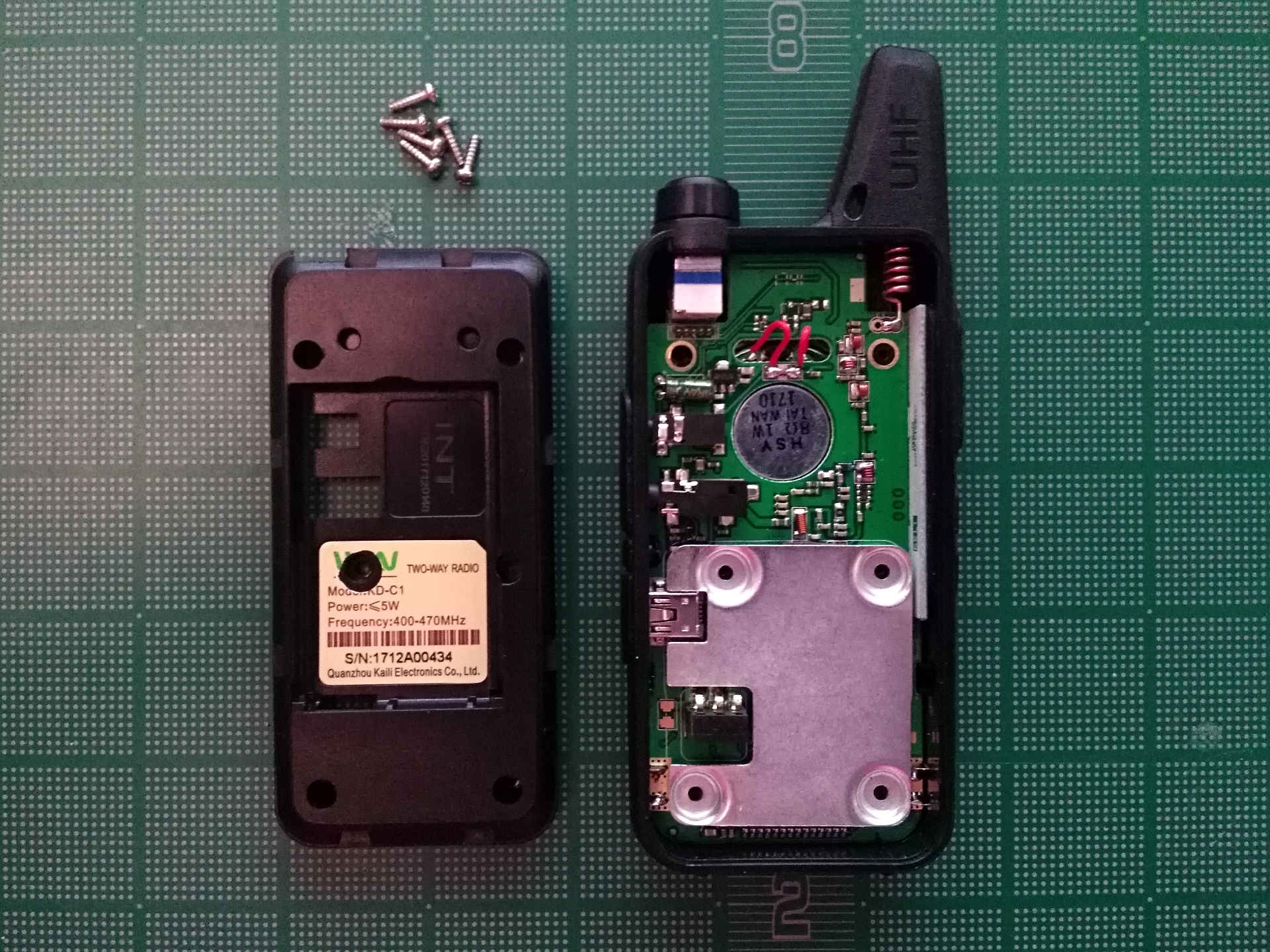
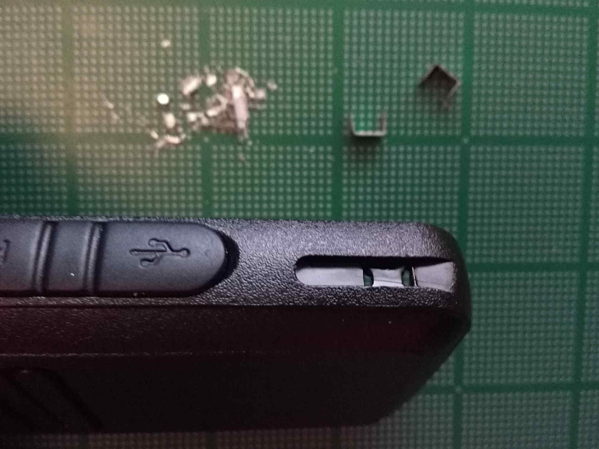
This is the point where the teardown I found stopped. The radio charges via USB or in a charge cradle that connects to the PCB via metal contacts on the bottom of the plastic case. These metal contacts are soldered directly onto the PCB making removal from the case impossible without desoldering or cutting them.
I decided to take the risk of melting the case and used a ColdHeat portable soldering iron and solder sucker to detach the tabs. After using the solder sucker I was able to push the tabs through the holes they were installed in. I melted the case just a bit, but it shouldn’t be too obvious once the tabs are replaced.
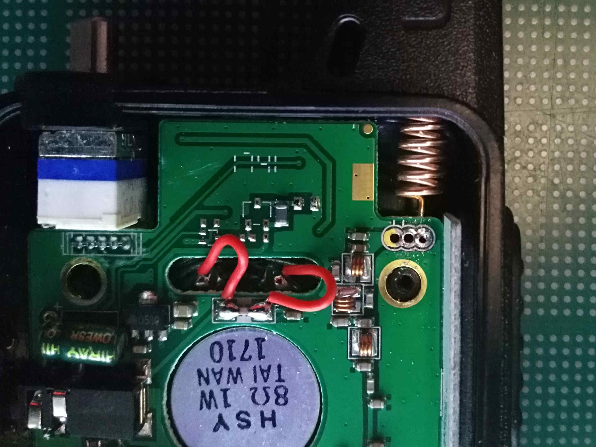
The antenna and speaker wires were also soldered to the PCB and needed to be desoldered before the board was removed. I wasn’t able to completely remove the antenna from the plastic case because it seems to be molded or glued into the plastic. To work around this I tucked the antenna under the board once I desoldered it.
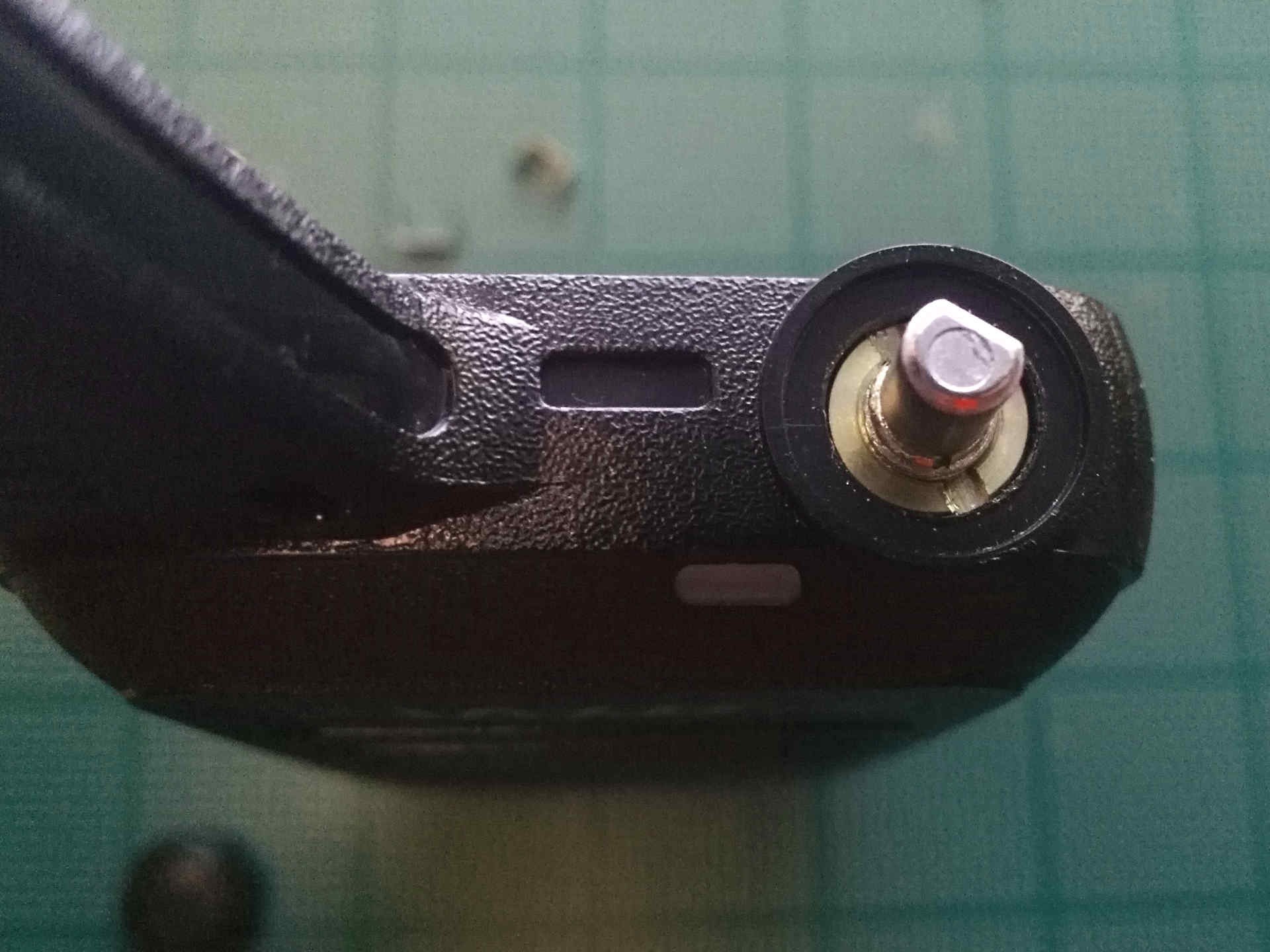
After the tabs, speaker, and antenna were disconnected the only remaining restraint was a nut hidden below the volume/power knob. I removed the knob by pulling it off the potentiometer. I was able to loosen the nut by wedging a flat head screwdriver in one of the grooves and pushing to cause the nut to spin counter-clockwise
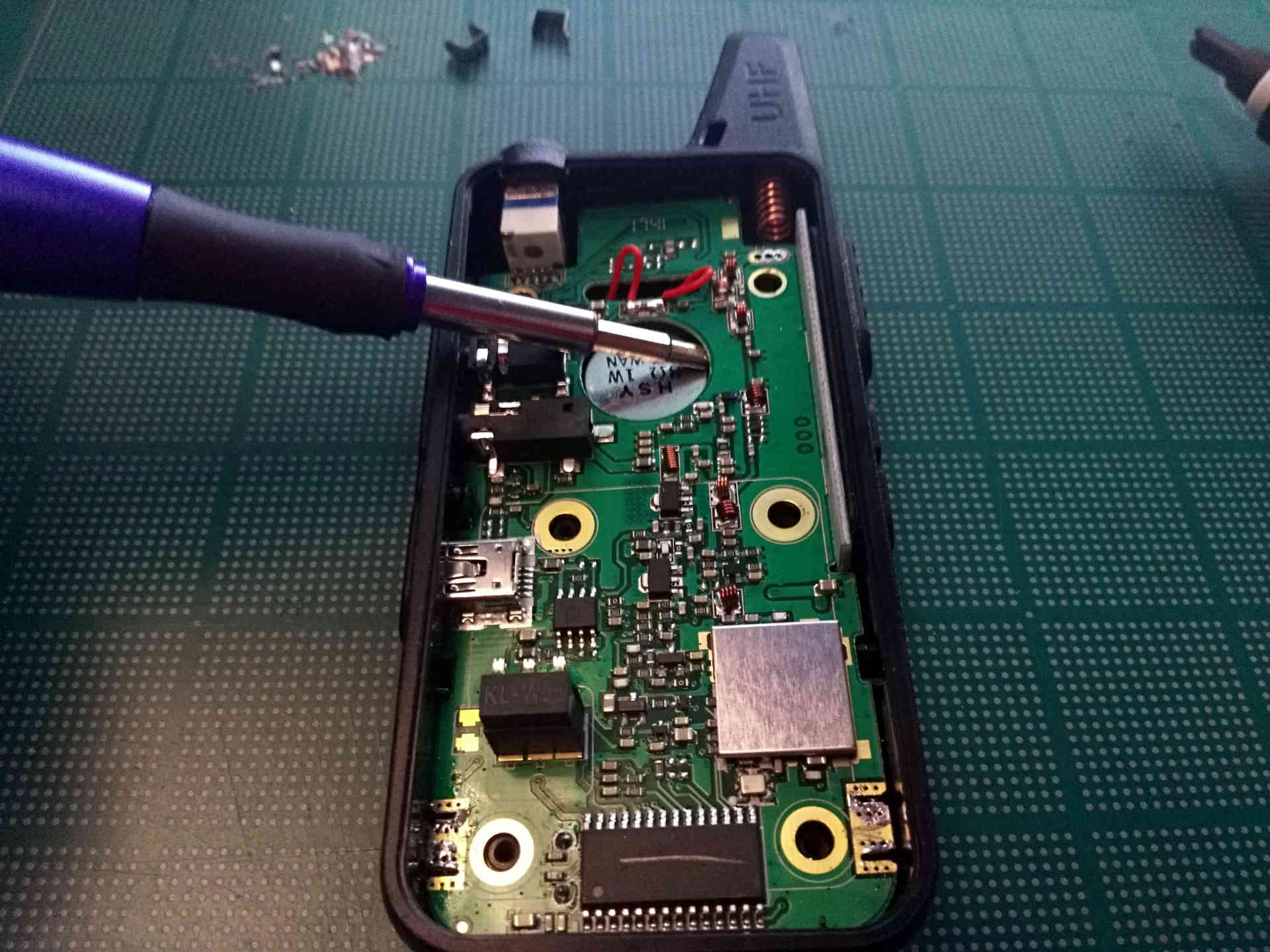
Once all impeding connections were been broken I (finally) removed the PCB from the case. I used a screwdriver to lift the right side of the board and pulled it out by the lower right corner. This step was a little tricky and took some patience.
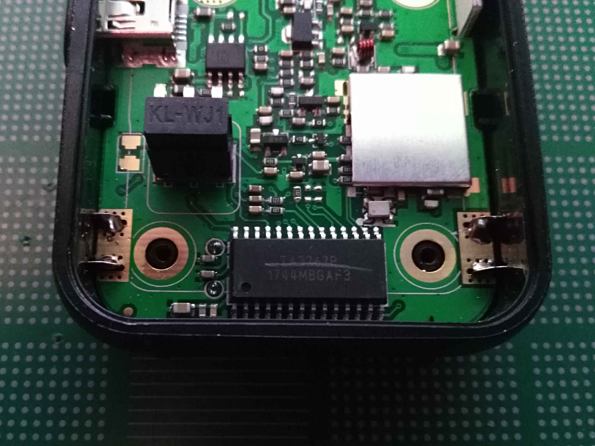
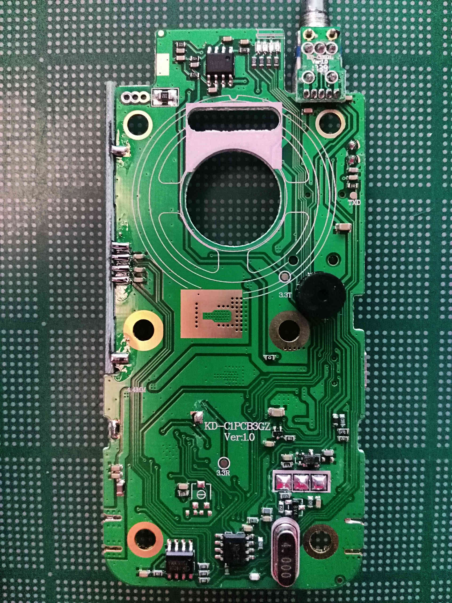
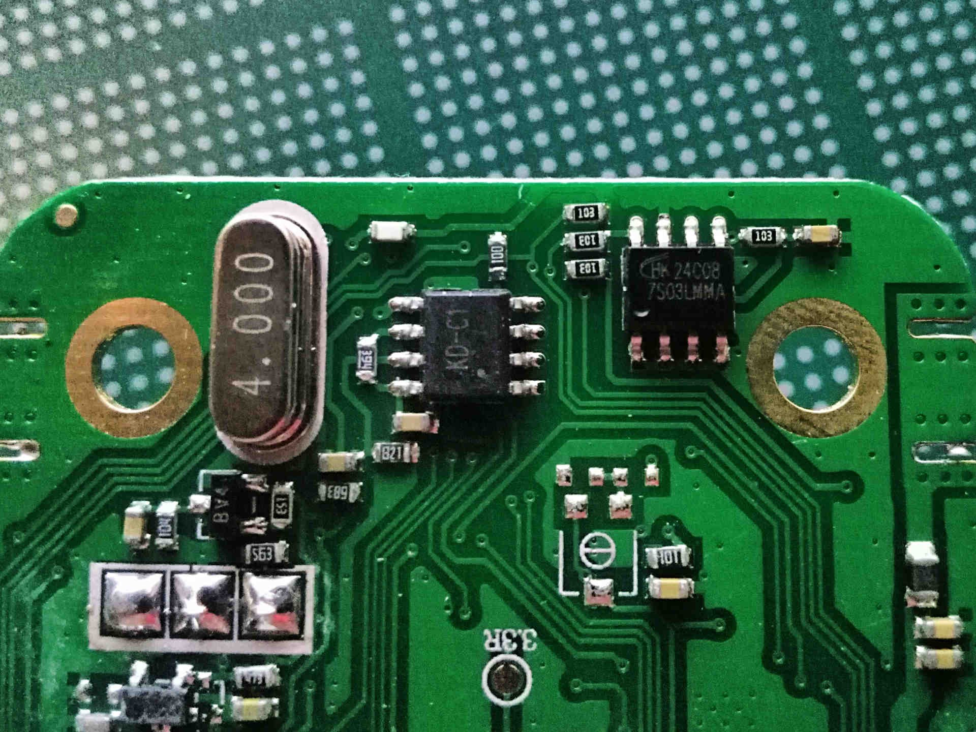
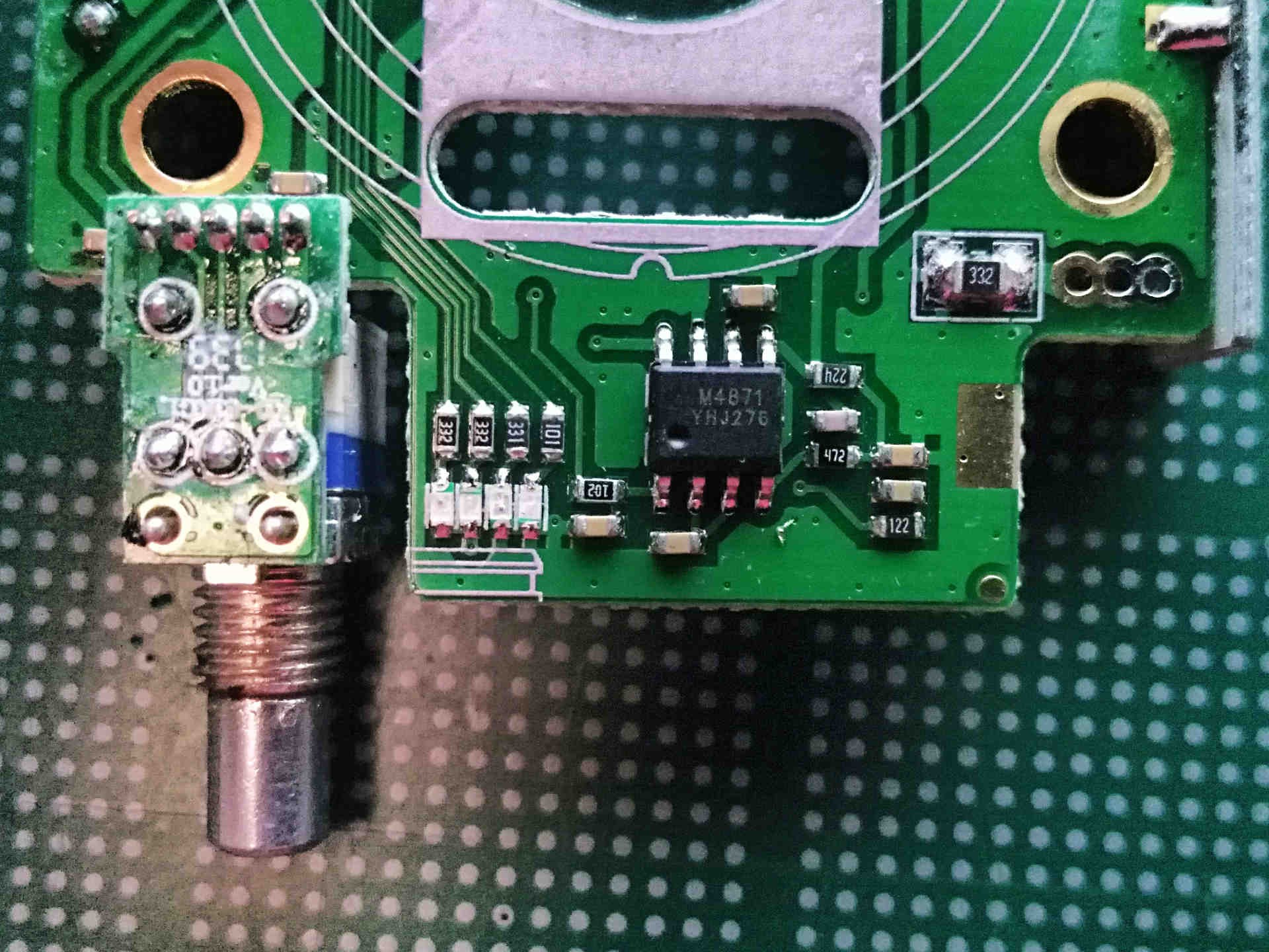
I took some photos of the board once I got it out. I tried to get clear shots of all the ICs and traces in case someone finds them useful.
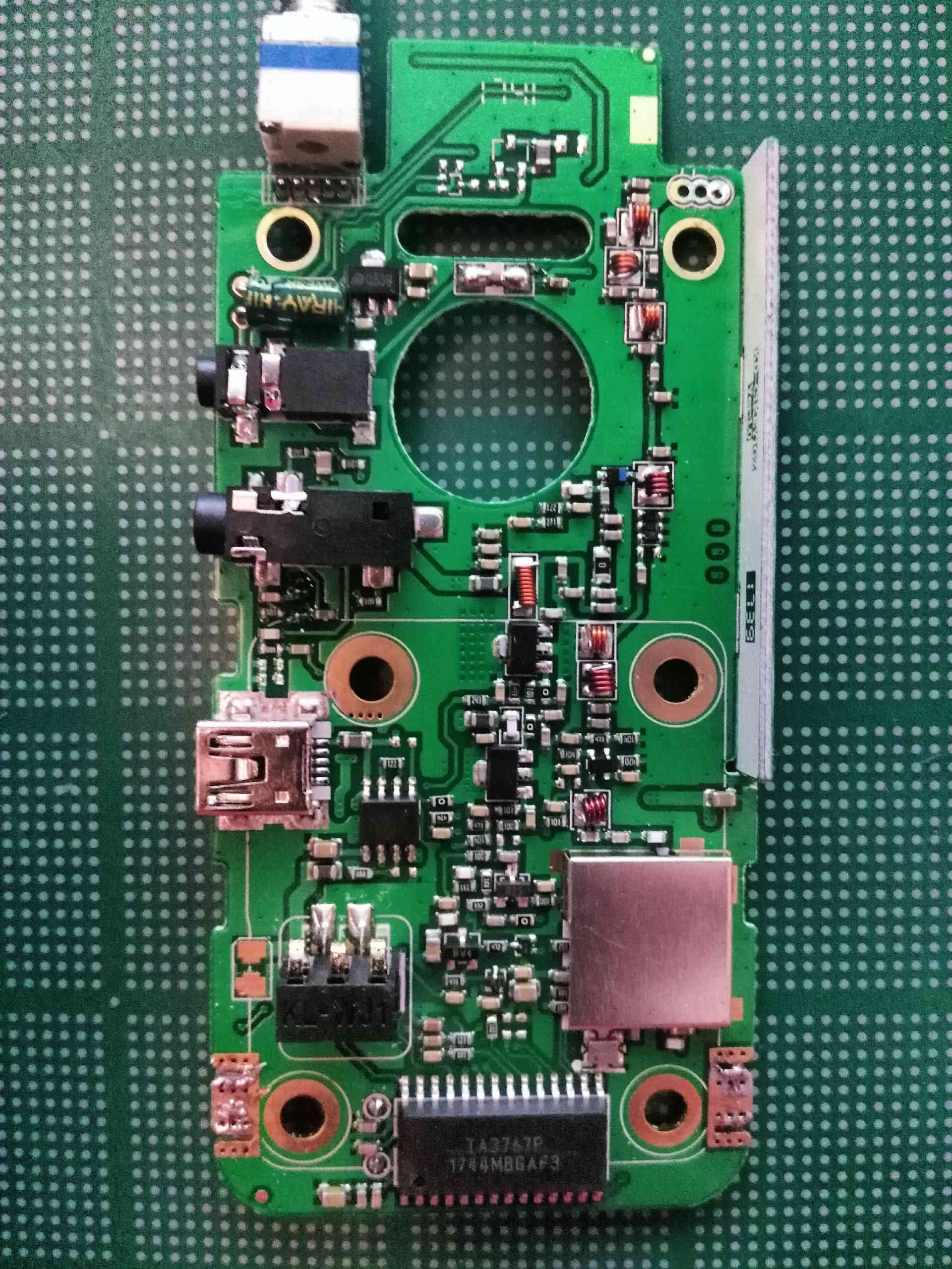
Here is a shot of the side of “font” of the PCB that is hidden by the case.
There are several 8-pin packages on the front of the board. One IC is labelled with the model number of the radio “KD-C1”, the other is labelled “HK24C08”.
This one is labelled “M4871”.
There is also what looks to be a custom microcontroller “TA3767P” and a radio transceiver IC “AT1846S” on the back of the board. I had to remove a metal shield to get access to the transceiver IC.
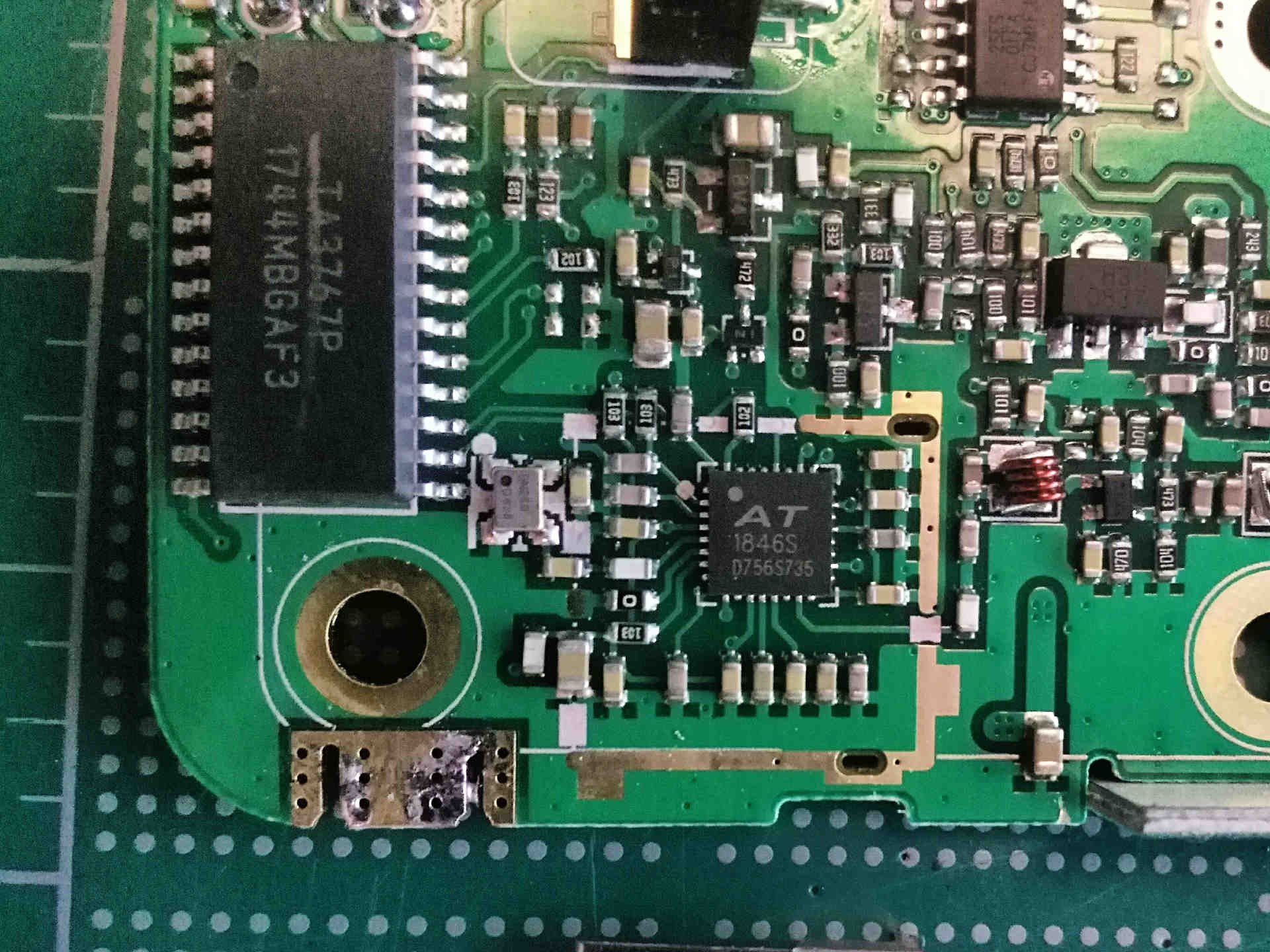
I didn’t come up with much searching for the AT1846S. I found a general description posted by a supplier, but I couldn’t find a datasheet. The general description states the IC is portable FM radio transceiver that works in the ranges 134MHz-174MHz, 200MHz-260MHz, and 400MHz-520MHz. At first glance this IC looks similar to the RDA1846 (aside from the “S” suffix) that is in the Baofeng UV-3R radios. The layout of the AT1846S on the PCB is similar to the pinout of the RDA1846 from its datasheet meaning the two might be pin-compatible.
This has been a promising teardown. I am pleased to find out that the radio’s transceiver IC might officially support 1.25m frequencies. Now I just need access to a spectrum analyzer and some radio testing equipment so I can get my hand dirty with modifications.