


Wiring It All Up
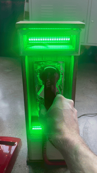
One feature I wanted in this project was “dynamic” lighting control when someone picks up the phone receiver. Lucky for me, the Viking phone had a multi-pole single-throw switch which was being under-utilized. One of the switches was terminated with cut wires which makes me wonder if the main body of the phone was recycled from a different product, or perhaps had more features planned at some point.
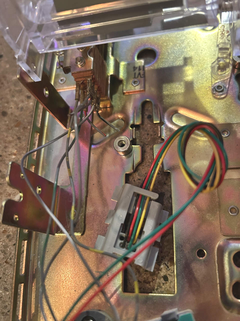
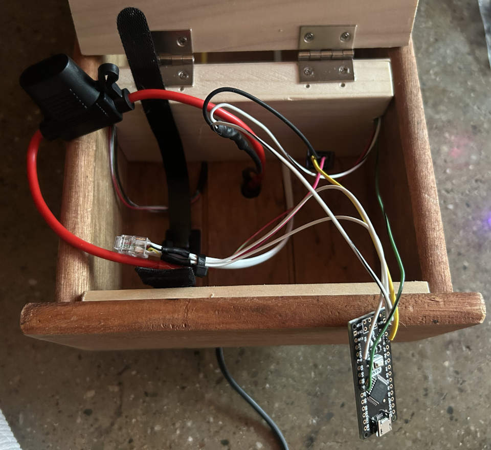
I removed the specialized wall plug from the phone and re-terminated the wiring with a standard RJ11 plug. I connected the inner 2 wires to the Viking phone electronics and the outer 2 wires to the hook switch. The reterminated wire was attached to the phone line in the enclosure using a coupler so that it could be removed easily if needed.
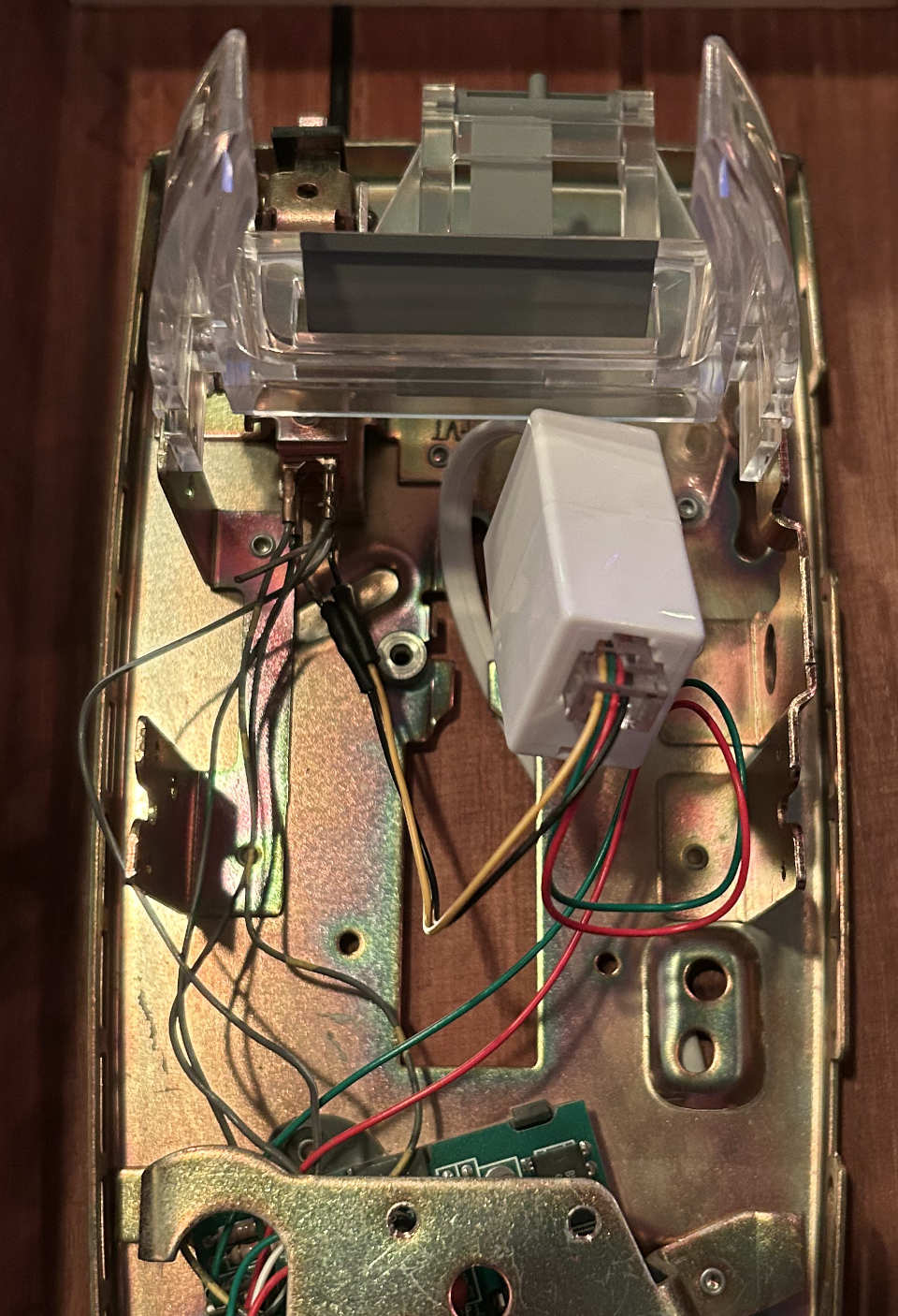
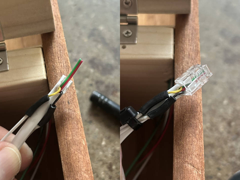
The other end of the phone line was split so that the outer 2 wires could be used outside of the ATA. Note that the following image shows an RJ10 connector because I grabbed the wrong one from my kit. It was later replaced with the correct RJ11 plug.
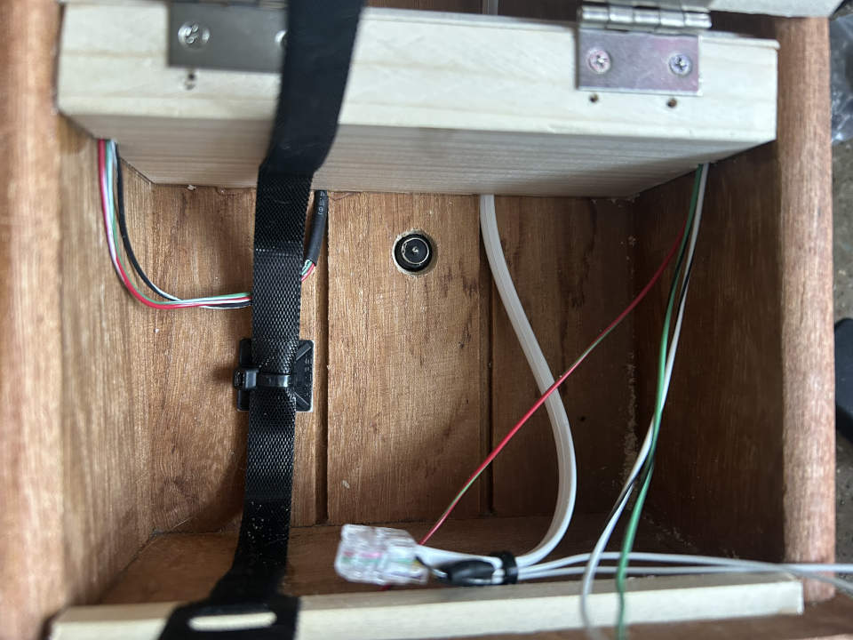
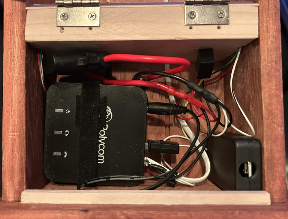
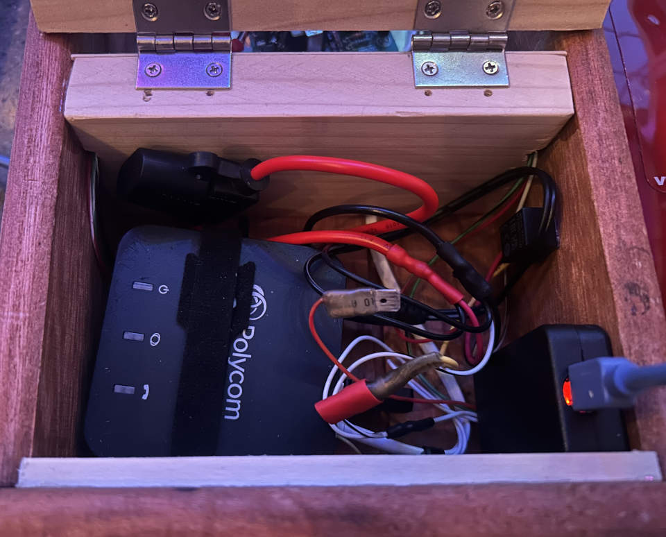
I didn’t want the ATA to just “float” in the bottom compartment, so I added a wire organizer and velcro strap to hold it down. Also pictured is a barrel jack inlet that supplies 12V from an external power supply. The jack was too short to secure with the included nut, so I ended up gluing it in place.
To drive the LEDs I added an Arduino Nano clone and a 5V DC DC converter so the enclosure could be plugged into a single 12V external power supply. I also added an inline fuse holder to the incoming 12V line. I wanted to make some attempt at safety since the end-goal is to place this project in a public place. For now there’s a high-current fuse in it until I get a chance to measure the draw.
The output of the 5V converter was soldered directly to the 5V input of the Arduino.
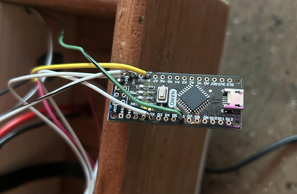
Here is everything test fit in the bottom compartment. The Arduino was placed in a small plastic enclosure and secured with double-sided automotive emblem tape (it’s what I had on hand and it has a very strong grip).
I plugged a USB cable into the Arduino to program it and the entire strip of LEDs lit up dimly. This was the result of the USB power back-feeding the 5V DC DC converter which is no good. I opted for the simple solution of adding a spade connector to allow separation of the 5V converter from the Arduino while programming it.
I hacked up a simple test program based on the one from the previous log entry to test the hook switch. A simple 2-color demo was enough to show the switch hook worked.
Here is the complete diagram of all the wiring. The colors were chosen to better show connections; the actual wire colors used are not reflected.

All that remains now is finishing up the physical enclosure and writing some LED driver code to add some flair.