


A Box of Opportunity
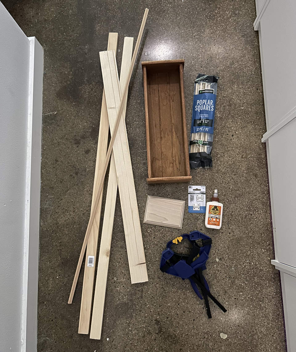
I am bad at working with wood. The tools used in this log are ones I had on hand in my small apartment: a hand saw, a cheap mitre box, and some clamps. With that said, I’m happy with the results (as janky as they are).
A loose phone and ATA are usable, but not nicely portable. I decided to utilize a wooden box that was part of a chocolate and candy gift set as a starting point for a payphone-esque enclosure. I added some “project wood” from my local Lowes to flesh out the rest.
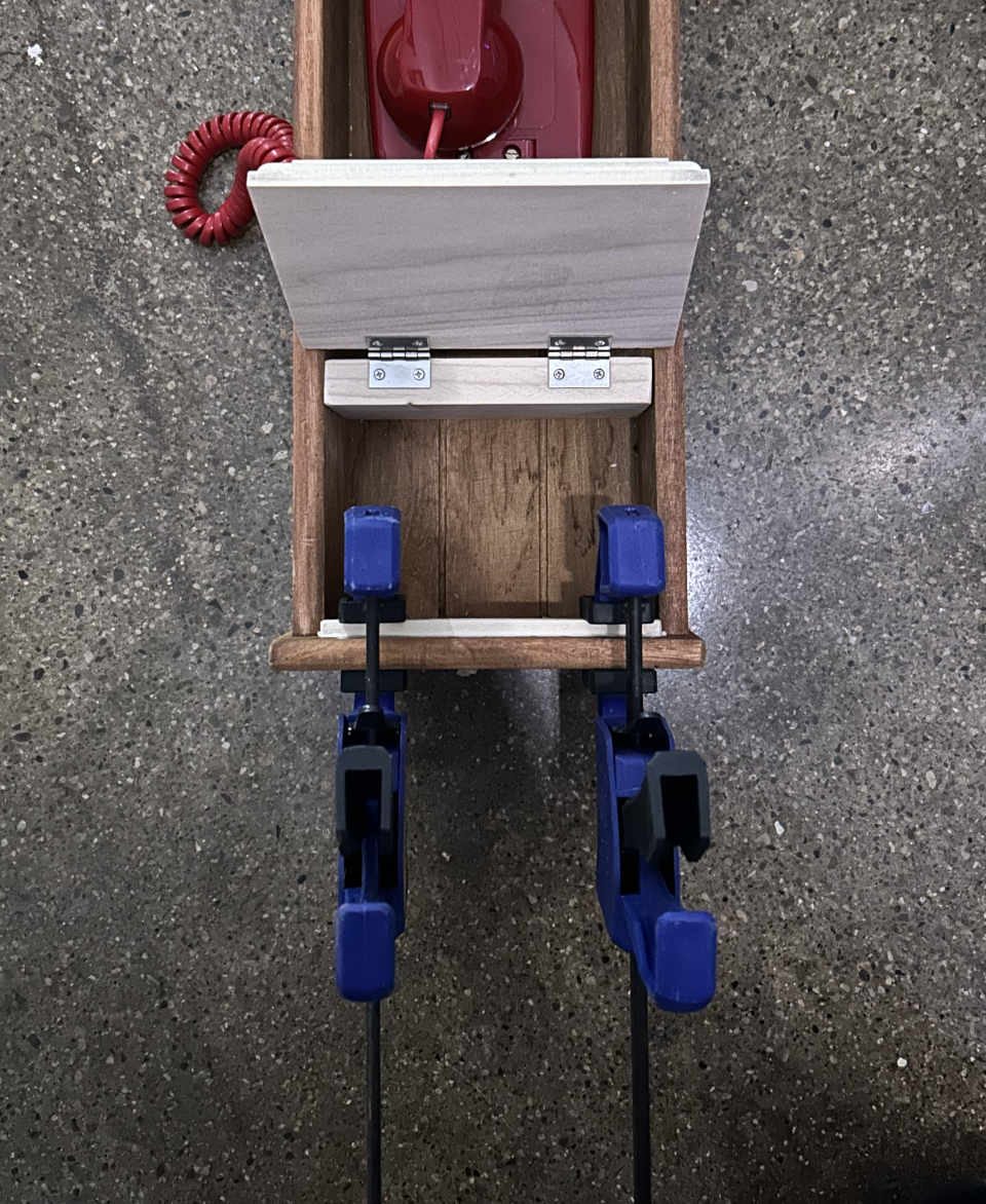
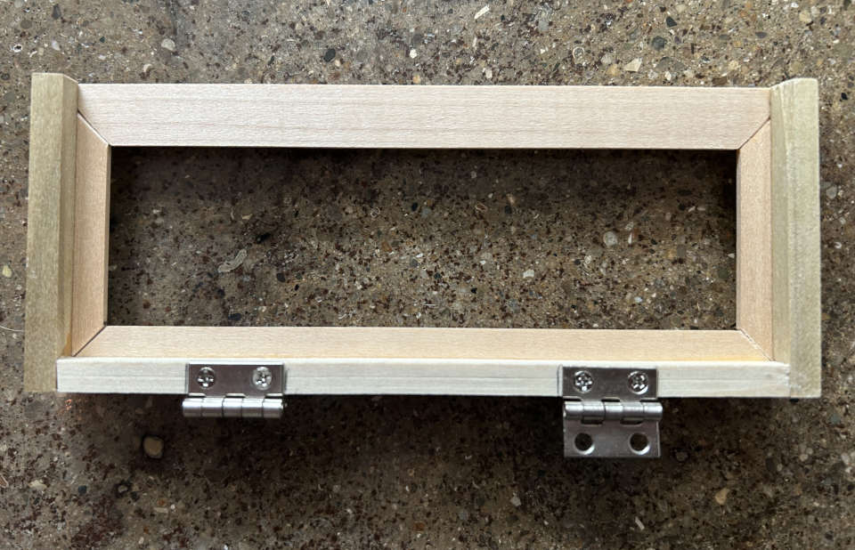
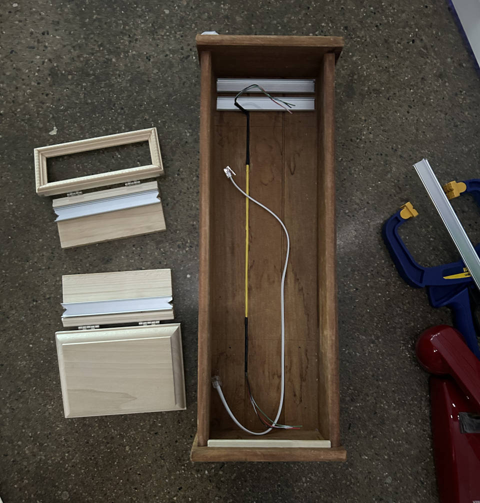
I divided the box into 3 sections. The bottom to hold the ATA and other electronics, the middle for the phone, and the top for a lighted panel to show artwork (think arcade marquee). I started with the bottom which was assembled from a section of board joined to a pre-cut beveled piece of wood by hinges.
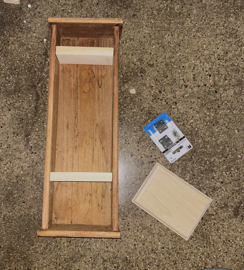
The bottom compartment will eventually be secured by a lock. A small piece of wood was glued in to align the door when closed.
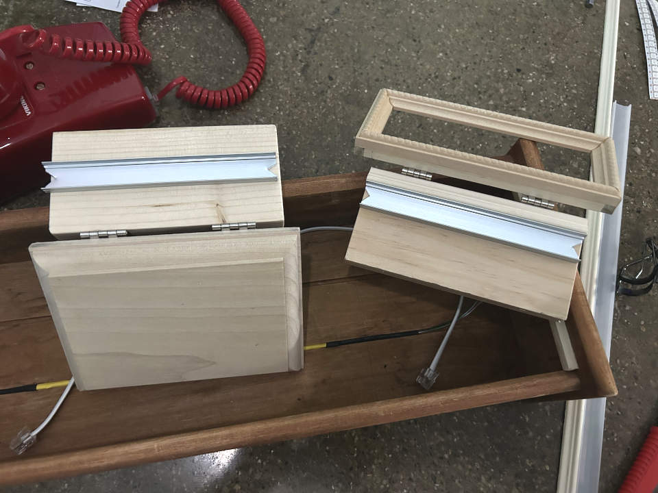
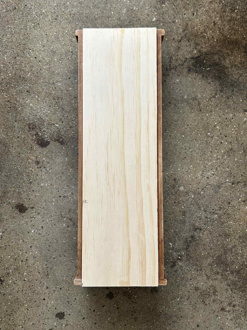
Initially, I cut the same thickness of board for the top compartment as the bottom (shown below), but later swapped it out for a thinner one to keep it from obscuring the frame built to cover the lighted area.
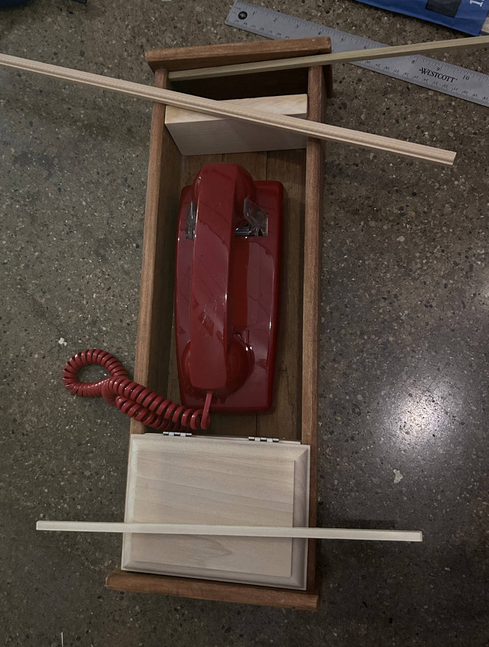
I assembled a small frame for the upper compartment by gluing together some sections of decorative moulding.
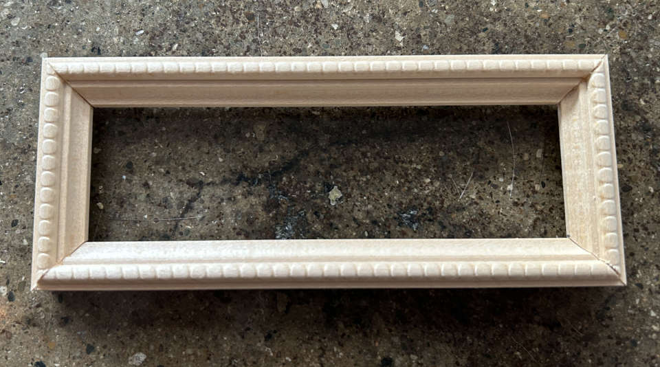
The frame was reinforced by gluing some small pieces of wood to the back. These pieces will later be used to hold translucent artwork in place.
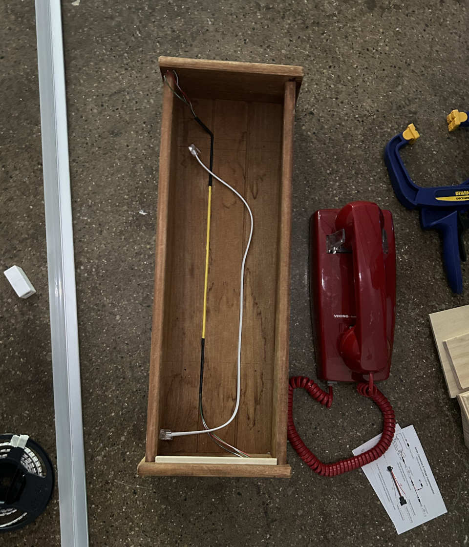
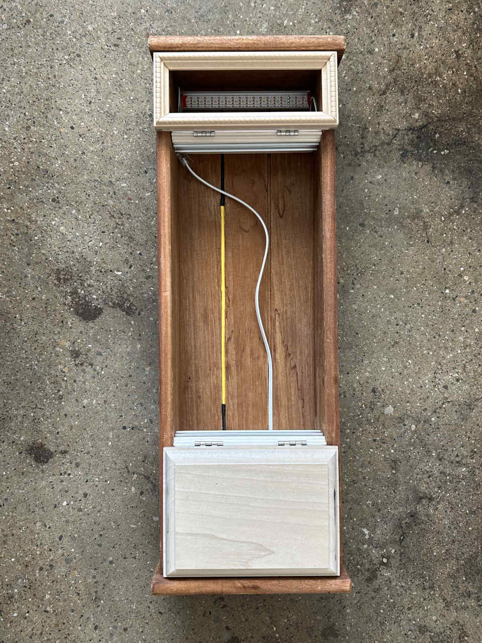
Cables were routed in the channels of the base box before installing the dividers. The cable on the left is 3 wires within shrink tubing that will be used to connect addressable LEDs in the top compartment with a microcontroller in the bottom. The cable on the right is a 4-wire phone line that will be used to connect the phone to the ATA.
In addition to the top lighted area, the phone will also be illuminated from the top and bottom by additional LED strips. I had some channels left over from installing some lighting at home, so I used that along with some moulding to hold the additional strips.
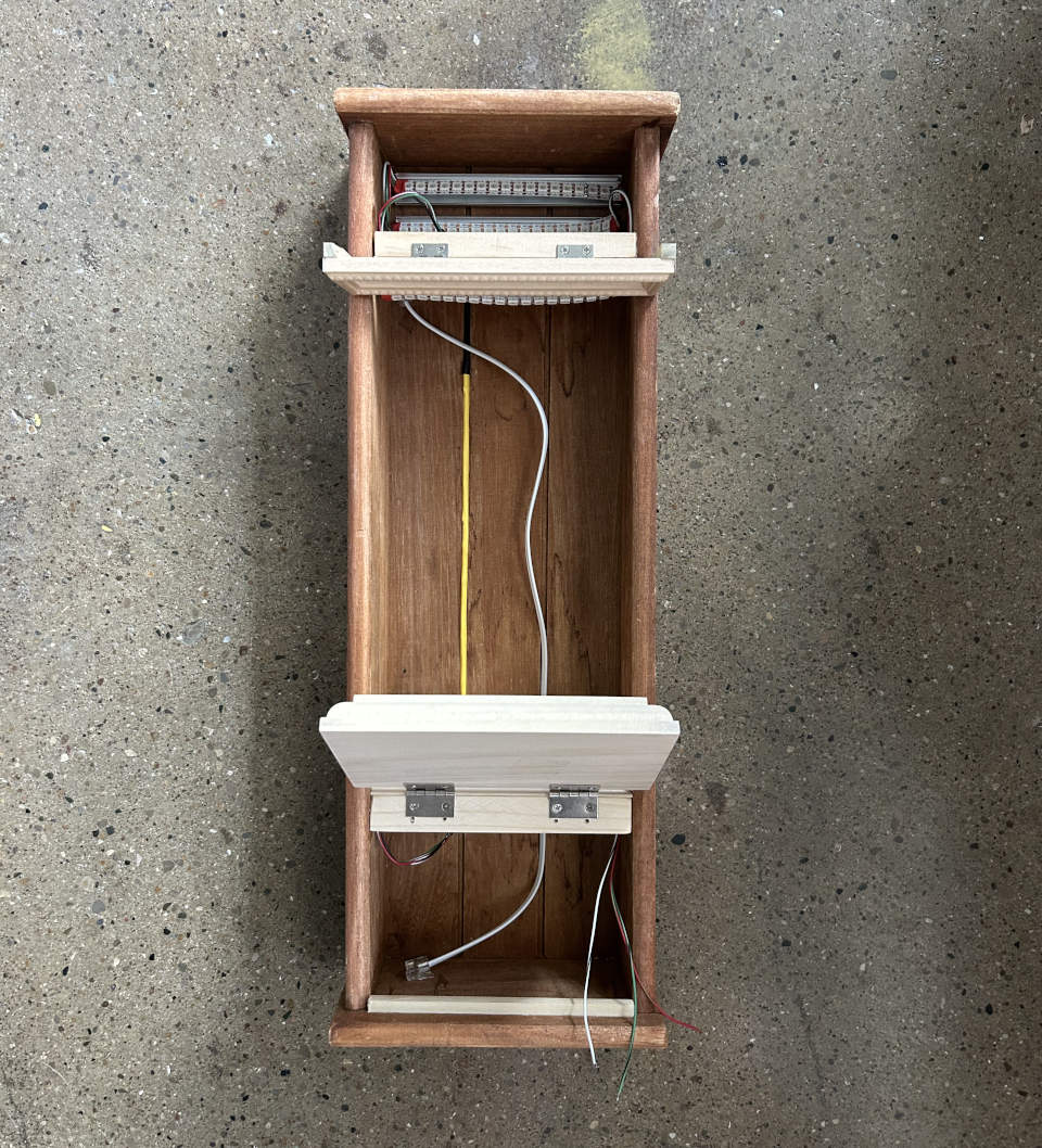
Notches were cut in the channels and compartment dividers to allow routing of wires to connect LED strips together.
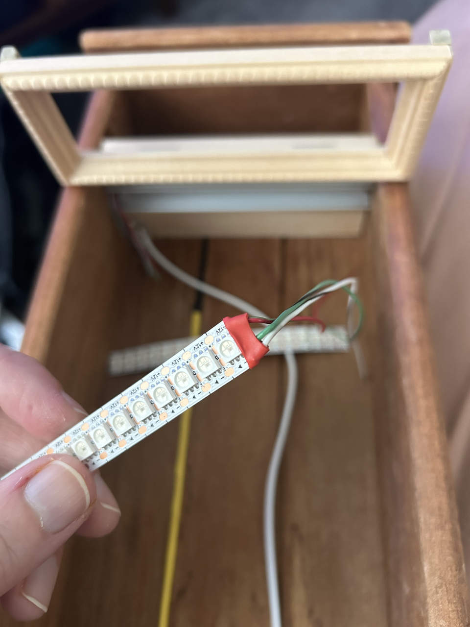
All of the individual LED strip segments were joined into a single run. I was worried that the solder points at the end of each strip may short against the aluminum channel, so I placed heat-shrink tubing on both ends of each segment. I wanted a very dense strip and ended up going with a 3 foot strip of WS2815 LEDs from BTF-LIGHTING. Each section has 18 LEDs.
The dividers were glued into the base box after installing the LED strips and phone wire. At this point the LED strips weren’t adhered as I wanted to test them first.
I used the example program from the Adafruit NeoPixel library running on an Arduino Nano clone to confirm the wiring was correct.
The back “wall” of the base box turned out to be thinner than I liked, so a thin piece of wood was glued to it for reinforcement.
With everything tested and glued, I peeled the adhesive backing on the LED stips and stuck them to the channels.
The box is still incomplete at this point, but far enough along to start working on the electronics.